- 您现在的位置:买卖IC网 > Sheet目录181 > 2938633 (Phoenix Contact)POWER SUPPLY 30A 24VDC
QUINT-PS-3x400-500AC/24DC/30
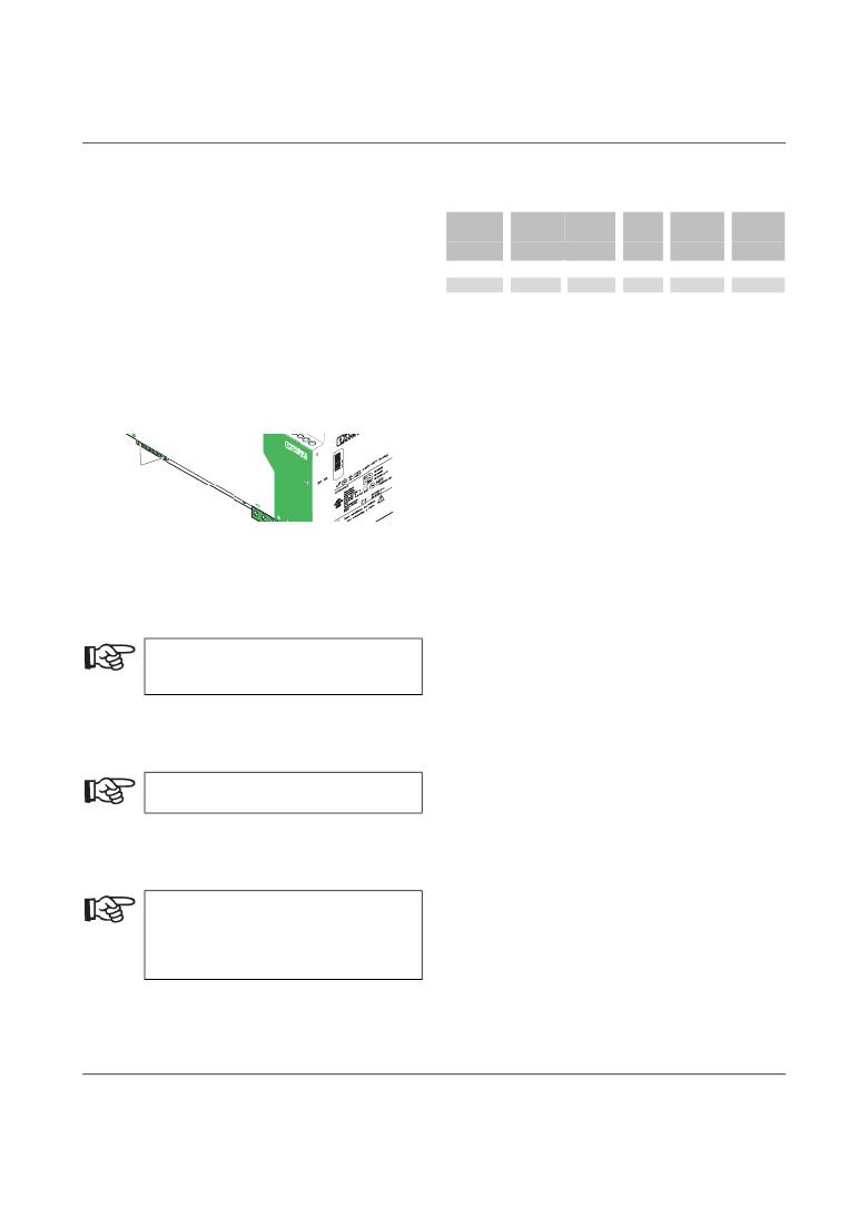
Connection of the Connecting Cable
Use a screwdriver with the correct blade width for wiring.
The cable cross sections listed in the table on the right can
be connected.
Solid
Stranded
[mm 2 ]
AWG
Torque
[Nm]
Stripping
Length
[mm]
Input
Output
Signal
0.2...6
0.5...16
0.5...16
0.2...4
0.5...10
0.5...10
25...10
20...6
20...6
0.5...0.6
1.2...1.5
1.2...1.5
8 mm
10 mm
10 mm
3A
L 1 40
L2 -500
For reliable and safe-to-touch connections, strip the cable
ends according to the table.
Input (1)
The 3 x 400...500 V AC connection is made using the
Input
L1, L2, L3, and 5 screw connections.
C
0
V
L3
22 djus
8,5
1
A
,5-2 t
V
13
14
DC
OK
O C
Figure 8
Input
D
K
Ou
tp
ut
DC
24
V
30
A
Fuses
Three external thermomagnetic fuses are required to
protect the device. Even in the event of a phase failure,
continuous operation is ensured with nominal load.
If an external fuse is blown, this is most
probably due to a device fault. In this case, the
device should be checked in the factory.
Recommended Backup Fuse
3 x circuit breaker 6 A, 10 A or 16 A, Characteristic B
(or equivalent).
A suitable fuse should be provided for DC
applications.
Protecting the Primary Side
The device must be installed according to the specifications
of EN 60950.
It must be possible to switch off the device
using a suitable disconnecting device outside
the power supply.
For example, primary side line protection could
be used.
100035_04_en
PHOENIX CONTACT
8
发布紧急采购,3分钟左右您将得到回复。
相关PDF资料
2938646
POWR SUPPLY 40A 3X400-500AC 24DC
2938714
PWR SUPPLY 3A 100-240AC 5DC
2938727
POWR SUPPLY 20A 3X400-500AC 24DC
2938730
PWR SUPPLY 2A 100-240AC 24VDC
2938743
POWER SUPPLY 1A 2X15VDC
2938756
PWR SUPPLY 2A 100-240AC 10-15VDC
2938811
PWR SUPPLY 10A 100-240AC 12VDC
2938837
POWER SUPPLY 4A 24VDC
相关代理商/技术参数
29-3863P
制造商:AIM Cambridge Connectivity Solutions 功能描述:
2938646
功能描述:DIN导轨式电源 QUINT 3PHASE 24V 40A
RoHS:否 制造商:Mean Well 产品:Linear Supplies 商用/医用:Commercial 输出功率额定值:960 W 输入电压:180 VAC to 264 VAC, 254 VDC to 370 VDC 输出端数量:1 输出电压(通道 1):48 V 输出电流(通道 1): 输出电压(通道 2): 输出电流(通道 2): 输出电压(通道 3): 输出电流(通道 3): 尺寸:150 mm L x 110 mm W
29-3864P
制造商:AIM Cambridge Connectivity Solutions 功能描述:
2938695
制造商:Phoenix Contact 功能描述:MINI-PS-120-230AC/24DC/0.65BL
29387
制造商:Schneider Electric 功能描述:IMPULSE RELAY MX 200/240V CA 50/60H
2938714
功能描述:DIN导轨式电源 100-240AC 5DC 3A
RoHS:否 制造商:Mean Well 产品:Linear Supplies 商用/医用:Commercial 输出功率额定值:960 W 输入电压:180 VAC to 264 VAC, 254 VDC to 370 VDC 输出端数量:1 输出电压(通道 1):48 V 输出电流(通道 1): 输出电压(通道 2): 输出电流(通道 2): 输出电压(通道 3): 输出电流(通道 3): 尺寸:150 mm L x 110 mm W
2938727
功能描述:DIN导轨式电源 QUINT 3PHASE 24V 20A
RoHS:否 制造商:Mean Well 产品:Linear Supplies 商用/医用:Commercial 输出功率额定值:960 W 输入电压:180 VAC to 264 VAC, 254 VDC to 370 VDC 输出端数量:1 输出电压(通道 1):48 V 输出电流(通道 1): 输出电压(通道 2): 输出电流(通道 2): 输出电压(通道 3): 输出电流(通道 3): 尺寸:150 mm L x 110 mm W
2938730
功能描述:DIN导轨式电源 100-240AC 24DC 2A
RoHS:否 制造商:Mean Well 产品:Linear Supplies 商用/医用:Commercial 输出功率额定值:960 W 输入电压:180 VAC to 264 VAC, 254 VDC to 370 VDC 输出端数量:1 输出电压(通道 1):48 V 输出电流(通道 1): 输出电压(通道 2): 输出电流(通道 2): 输出电压(通道 3): 输出电流(通道 3): 尺寸:150 mm L x 110 mm W
